
In a world of AI slop flooding the internet, global conflict, and everything being sold as a major accomplishment on LinkedIn, I sometimes like a low-stakes project. Taking an afternoon or two to whip up something new and interesting can be really relaxing when you’re working at your own pace.
Most times I go for these projects, they involve hardware from AliExpress. There’s nothing better than knowing that, even if I really mess up, I will only be down by a few euros.
I’ve been practicing this philosophy for a long time, and it’s exactly thanks to it that I built the drivers for some BLE thermal printers and for Gicisky E-Ink displays. I had lots of fun experimenting with Bluetooth Low Energy, and I even learned some Flutter in the process.
With those projects being mostly complete, and with my innate desire to start new tasks, I set off in search of my next test subject on AliExpress. That’s when I stumbled across this:

Magnificent. A video camera with blatantly false specs, for just above €10? I had wanted to try circuit bending for a while, and my intuition was telling me I had just found the perfect candidate. In hindsight, I think I was right, but before we get to that, let me explain what I was trying to achieve.
Circuit bending
In short, circuit bending is the art of modifying the circuits in electronic devices, usually synthesizers and old cameras, to get audio and video effects out of them. By bridging parts of the circuit that were never meant to be connected, builders intentionally cause errors within the hardware, which they hope will result in something visually interesting.
Circuit bending is rarely an exact science. If you ever read a circuit bending tutorial, you’ll learn that a big part of the fun is in connecting random “known to be safe” pins and finding out what happens, even while treating the circuit itself as a black box.
I will cover more of how circuit bending works shortly, but for now, let’s jump straight into some practice.
The surgery
For this experiment, I opted for a (mostly) reversible, and very flexible, approach. The camera’s sensor connects via a 24 pin ribbon to the motherboard, so I decided to expose those 24 pins to the outside of the camera’s shell. This way, simply by using a patch cable, I can connect any combination of pins I want, to achieve exactly the effect I desire.
Most people will find the effects they like beforehand, and only expose a couple of switches to trigger them. That works too, but since this was my first go, I wanted to be able to test new effects at any time, even with the shell closed, and without additional soldering.
Looking inside
To open the shell, just remove the two screws at the bottom, then it’s a matter of freeing the plastic clips that go all around the shell. My go-to entry point is the MicroSD slot; just make sure to remove the card beforehand, and don’t jam your tool in too deep, or you’ll break the reader.
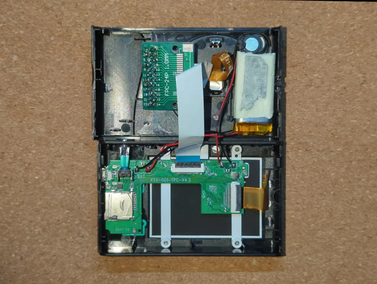
I wasn’t patient enough to take any shot of the camera’s internals before messing with it, so you will have to enjoy an after-the-fact recreation. If you notice anything weird, like a support looking as if it was cut out, or the battery being wrapped in painter’s tape, ignore it.
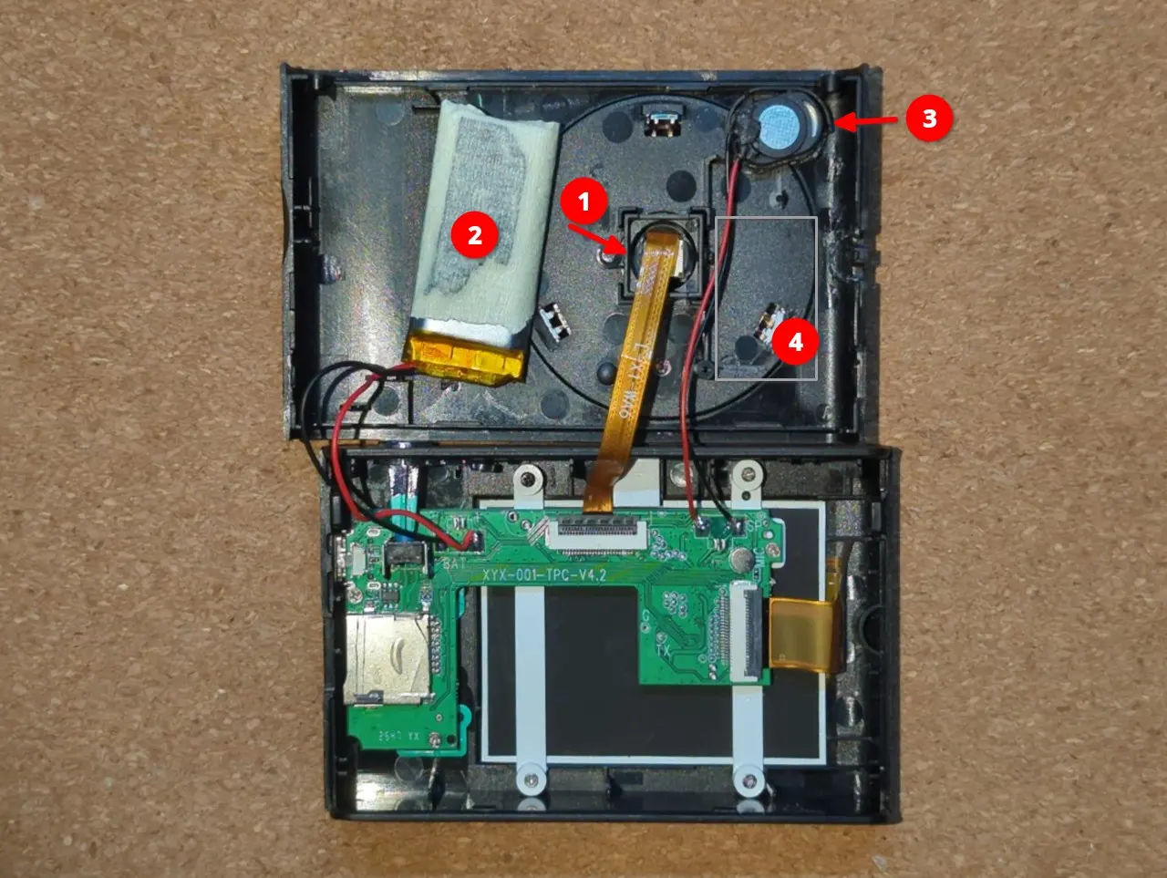
A few noteworthy things:
- The image sensor (CMOS) . This little thing is where the magic happens: this sensor captures the light from the environment, and turns it into a picture.
Fun fact: I have no idea what it is. I initially thought it would be a clone of the OmniVision sensors you normally find in ESP-Camera kits, as those are 24-pin as well, but it’s not, since GND is on pin 3 rather than 2. The writing on the ribbon (“L-X1-WA6”) doesn’t yield any results, not even on Alibaba. If you can find any information on it, please let me know! - The battery. If I recall correctly, it should be about 250 mAh. It’s not much, but it’s enough.
The only problem with the battery is its placement. It’s taking up precious space that we need to expose our camera pins. - The speaker. It doesn’t serve a great purpose within this camera, I usually mute it. If you ever decide to upgrade the battery, or that you need any more space within the shell, removing it would be a victimless crime.
- A dead weight, meant to give the impression of there being electronics inside the shell, rather than mostly air. I had already thrown it away when I took this photo.
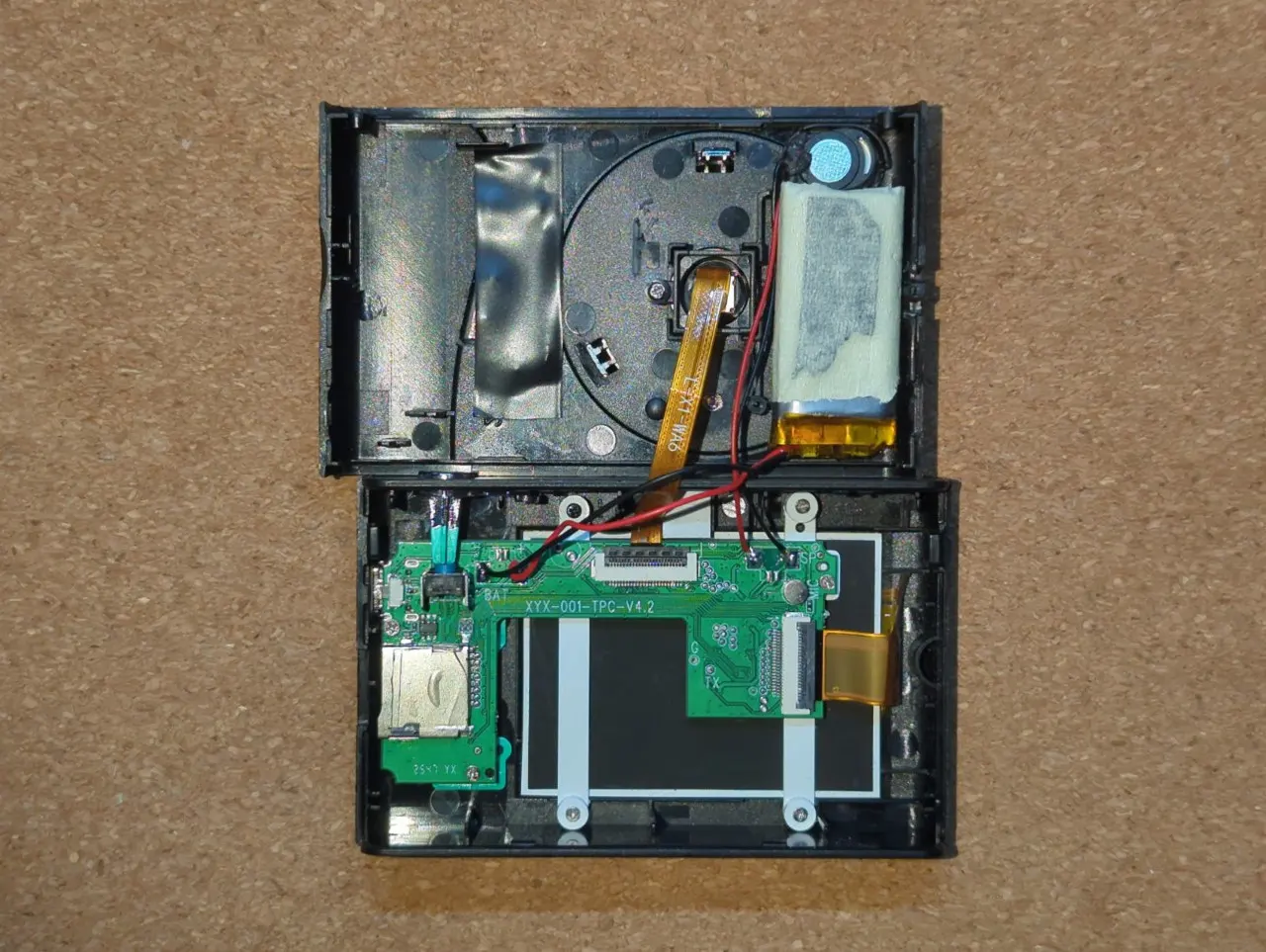
Making room
So obviously, a few things have to move, starting from the battery. That involves using flush cutters to remove one of the two support screws for the CMOS and a clip for the fake lens, shaving a bit of the speaker’s housing, removing the plastic for the lanyard loop, and (you guessed it!) removing the dead weight.
This gives us just enough space to move the battery near the speaker, therefore freeing up most of the other side of the shell to expose the pins.
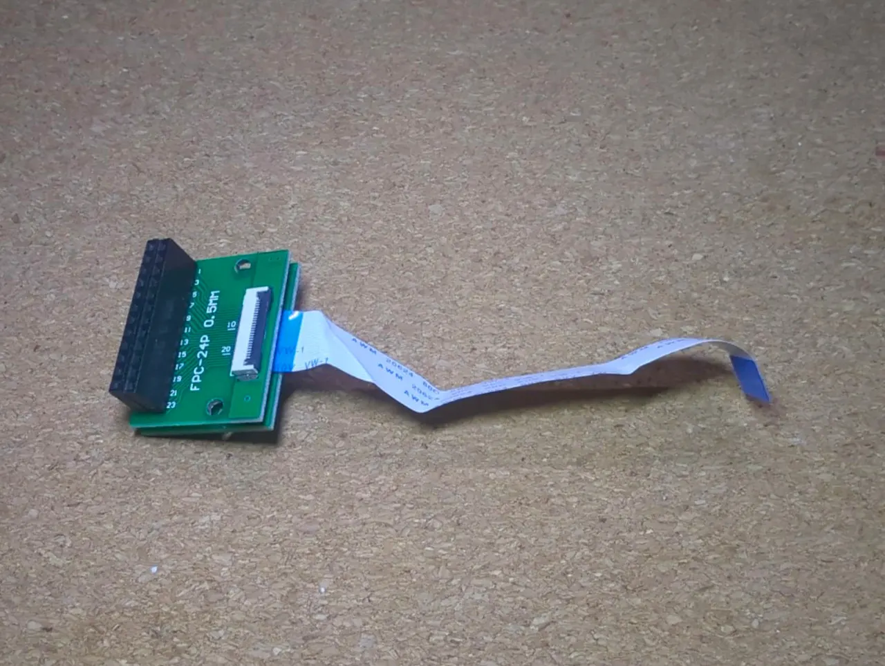
Creating the patchboard
Now comes the clever part: how do we expose the 24 pins to the outside, without any insanely tedious soldering? The FPC connector has a pitch of just 0.5mm, so I chose from the start not to solder directly onto it.
Well, it turns out that there are some 24-pin FPC breakout boards, which are a true lifesaver for us.
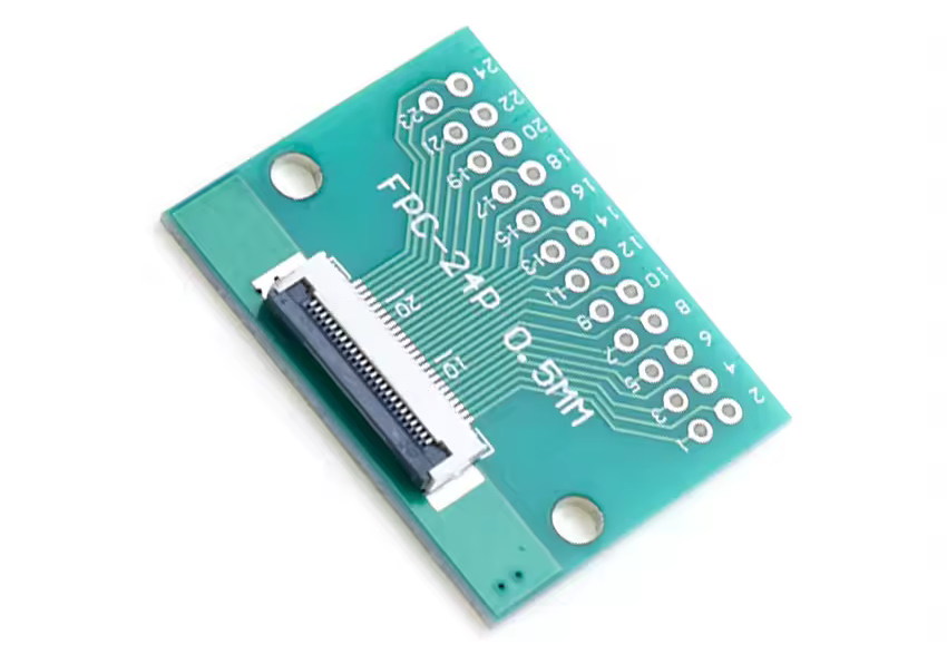
Image credit: Cltgxdd Store on AliExpress (yep, it really is their name)
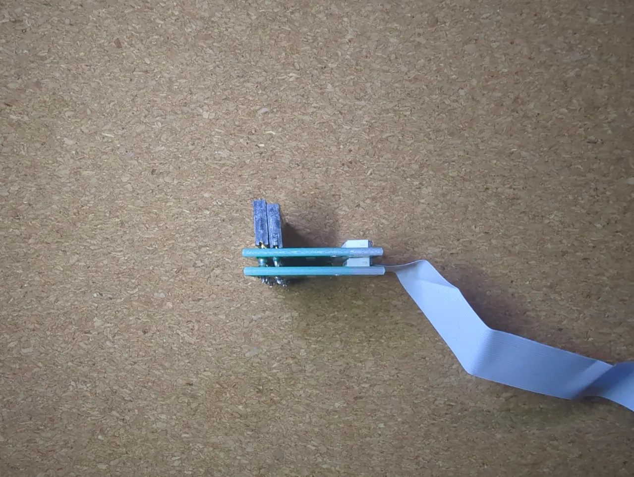
These boards have an FPC connector on one side, and standard-size holes for pin headers on the other. Through the magic of buying two, stacking them, and using long-legged female pin sockets to connect the two layers together, we have created our “patchboard”.
 |  |
|---|
Make sure to either plug your ribbon cable into the bottom layer before it’s soldered in place, or leave enough clearance for the flap on the bottom layer to open.
These sockets will stick out on the outside of the camera. By bridging them with a male-to-male patch cable, we can bridge any of the sensor’s 24 pins as we want.
Testing and reassembly
Now it’s time to plug our concoction into the camera. We remove the CMOS cable from its original position on the motherboard, and replace it instead with the ribbon from the bottom layer of our sandwich. Then, we plug the CMOS cable into the FPC connector on the top of our breakout sandwich.
Test that the camera works without any patch cable, then try bridging a couple of pins, and see what happens:
- Nothing happens? It’s okay. You may have shorted two identical logic states, two grounds, or two powers. Or maybe that input pin is being ignored at that moment. There’s no way to know without a datasheet, and we don’t have one.
- The video freezes? That’s a crash, but don’t panic. Remove your patch cable, power cycle the camera, and it will (most likely) be alright. Try a different combination.
- Colors go glitchy? You can pat yourself on the back; you’ve just circuit-bent a CMOS camera.
After you’ve checked that the camera works both with and without circuit bends, it’s time for the finishing touches.
Cut a window through the case, near the CMOS sensor. Remember that it’s best to measure twice and cut once. Pay particular attention to the full footprint of the breakout board, and whether it will hit against the shutter button on the other side, when the shell is closed. Once it’s done, stick the pin sockets through, the result should look something like this:
Use tape or hot glue to hold the patchboard and the speaker in place, then carefully close the shell, while making sure that no component is being punctured, and the ribbon cables aren’t being stressed. And, just like that, it’s done!
The result
I’ve taken my circuit-bent camera on a couple of walks and photographed whatever caught my eye. I’m no photographer, and, regardless of what combination of pins we use, it’s still a €10 camera with a no-name CMOS, so I didn’t expect to win any awards.
With that in mind, the results are not bad at all. All photos you will see are unedited, dumped straight from the MicroSD of the camera.
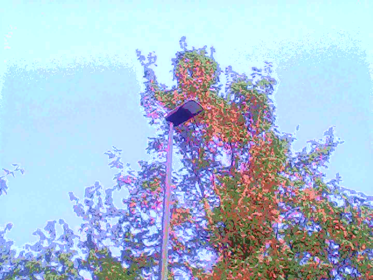
The posterization effects
 |  |
|---|---|
 |  |
I think these are pretty good, even though the sky in the first and 4th photo is really blown out. I got most of these “posterization”-type effects by connecting pin 8 to others (like 7-8, 5-8, 10-8), with all the combinations being slightly different.
These photos were shot in the late afternoon, not at sunset, so the vivid purples and warm tones are entirely the glitch’s doing.
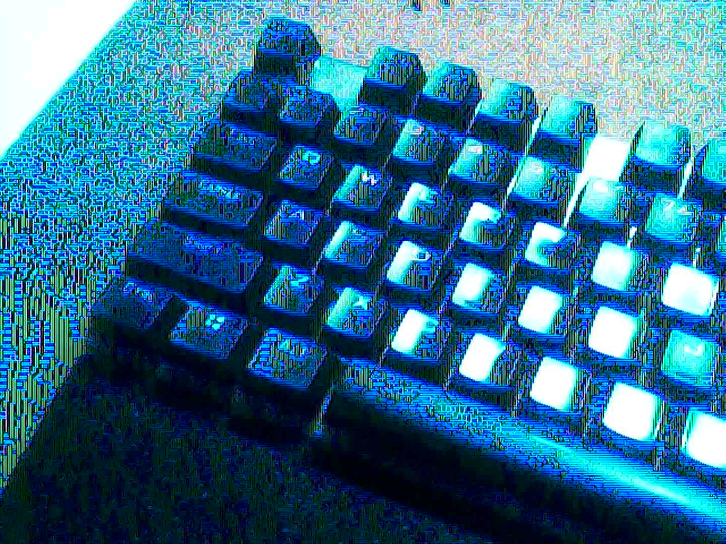
The drug trip effects
 |  |
|---|---|
 |  |
 |  |
These effects look much more aggressive: they’re sharp, discrete, dry. I don’t think they’re bad at all, but they’re obviously a different genre, and a much more abstract one at that.
You can get most of these effects by shorting pin 6 with something else, like 6-21, 6-24 or 6-4. The last photo, a field with hills in the background, amused me especially because of how the sky became quantized.
The semi-permanent effects
 |  |
|---|
These two are special, because the effects persist even after removing the patch cable, until the camera is rebooted. Both are triggered by shorting pins 13 and 17, with a quick tap triggering the first filter, and a longer hold resulting in the second (or, sometimes, a crash).
Although it’s hard to know for sure what’s going on, I’m guessing that by shorting these pins, we’re modifying the configuration of the CMOS. That’s right: CMOS sensors have a very small amount of embedded memory, which controls stuff like gain and white balance, and it looks like we tampered with them somehow. When we restart the camera, these registers lose power, therefore their data, so the original state is recovered upon the next boot.
I like the first filter in particular. It’s very neon (the light was actually warm in real life!), and the bright green glitches make for an insanely eerie feeling.
The theory
You’ve seen the glitches, but now it’s time to ask ourselves: how do they work? And why do they look so different from other circuit-bent photography?
The answer lies in how image sensors work, and how they respond to the errors we’re causing by circuit bending.
Older cameras don’t use CMOS, but CCD sensors, which “speak” in analog signals. Analog circuits have no concept of an “error”: just like how a VHS cassette plays regardless of how degraded its magnetic tape is, the CCD sensor does not complain if we twist its colors beyond recognition.
Newer cameras, like the one I got, use CMOS sensors, which makes them a bit trickier. Because they are digital, the errors we cause can be found and corrected. As we short the pins on a CMOS, we’re relying on the sensor’s communication protocol to not fix the error we’re causing, or recovering it in an interesting way. Luckily for us, our camera does that, but we need to tread carefully: if we generate too big of an error, the sensor will crash.
CCD and CMOS bending are very distinct visually. CCD is smooth, soft and wavy, just like VHS artifacts; CMOS is discrete, sharp and harsh, because it comes from a manipulation of digital signals.
I personally find CCD bending to be more visually interesting. This time, I opted against it just for a matter of convenience: as we saw, this toy camera was very easy to work on; real CCD point-and-shoot cameras are much more complex devices. In my future experiments, I will probably try one, but since this was my first experience in this world, I chose to keep it simple for now.
Conclusion
All in all, I’m very satisfied with how this project turned out.
I had fun making the patchboard, taking a bunch of glitchy pictures, and writing this blog post. I’m still having fun in trying more pin combinations, seeing how different effects work in different light conditions, and adding potentiometers to the mix.
I will likely share my circuit-bent photos somewhere online, but I don’t foresee them becoming particularly successful. I’m obviously not starting a career in photography any time soon, but that’s kind of the point: it’s a pet project. How well it goes is not a function of any measurable metric, but of how I feel about it.
I will probably try CCD bending in the future, because it seems more challenging, therefore more gratifying. I have already picked a sacrificial victim; when I decide to start planning the next surgery remains to be seen.
If you’ve read up to this point, and are wondering whether you want to do something like this yourself, my suggestion is: do it. It’s cheap, it’s novel, it’s fun. It’s very low stakes.
But if you really want to enjoy the process, I suggest you do it your own way. Maybe get another camera body, and see if the CMOS acts differently, or find another way of exposing the effects to the outside of the shell. The best part of this project, in my opinion, was the tinkering, not the photos, so while you could easily follow this blog post as a tutorial, I don’t really recommend it.
Either way, let me know how it goes. I’d be glad to hear how you’ve managed to improve over this little experiment of mine.
Shopping list
A word of caution: if you decide to get yourself a CCD camera, don’t buy it on AliExpress. It seems that the “CCD” keyword went trending thanks to some sort of retro digicam craze, so sellers are plastering the word everywhere, even if it doesn’t belong. Even the listing for my camera had it, despite clearly being CMOS. Go to your local used market and look for some point-and-shoot cameras from the early 2000s, you’ll find plenty of great options for around €10.
Even if you decide to follow this post as a tutorial, you might not be able to replicate everything I did exactly.
Inexpensive products like this toy camera are known not to be set in stone. Manufacturers are always looking for cheaper components to cut costs, and are known to sneakily push revisions. Even if you buy from the links below, and the listing photos look the same, you might end up with a completely different device internally, so be prepared.
I was in no rush to do this project, so at first I bought the camera, opened it and drafted a plan, then I bought the components for the circuit bending itself. I recommend you do the same, especially if you opt for a different camera body.
As always, this post does not come with any warranty. Even if you follow it exactly, your camera may break at any time (we’re not doing it any favors by shorting random pins, you know) and that’s on you.
I have chosen to provide both affiliate and non-affiliate links to AliExpress. Affiliate links allow me to earn a small commission on the sale of these items, and are a great way of supporting the blog without spending a penny (the price is the same in either case). If you choose to support the blog, thank you.
| Product | Note | Non-affiliate Link | Affiliate Link (Thank you!) |
|---|---|---|---|
| Camera body | 🔗 | 🔗 | |
| 24 pin FPC breakout board | Select the “24P” variant | 🔗 | 🔗 |
| 24 pin FPC ribbon | ”0.5mm pitch, 24 pins, 10cm, reverse direction” worked well for me | 🔗 | 🔗 |
| Female long pin socket | 1x12P | 🔗 | 🔗 |